01 / MARKER
Boom
Sections, folding geometry, and the published operating reach.
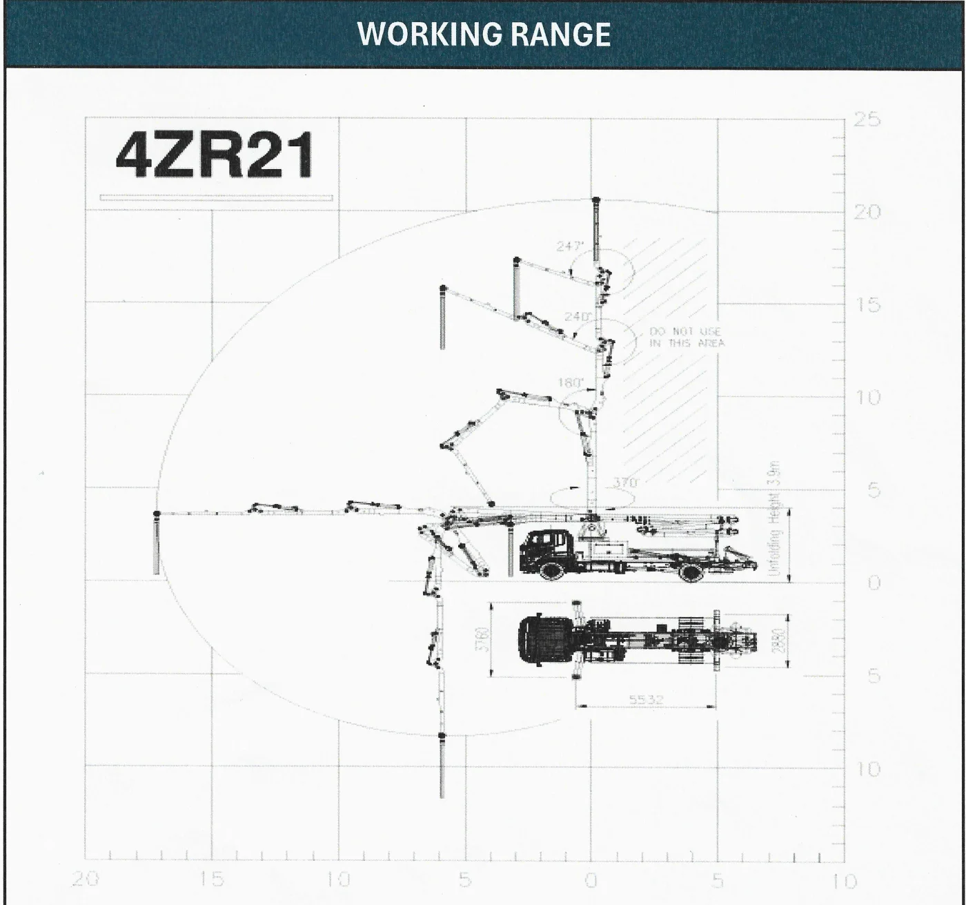
- Boom sections
- 4
- Folding type
- ZR-fold
- Maximum vertical reach
- 21.2 m / 69′ 7″
- Maximum horizontal reach
- 17.2 m / 56′ 5″
- Unfolding height
- 3.9 m / 12′ 10″
HR CONCRETE PUMPS
21 m 4-section ZR-fold concrete boom pump
FULL MODEL DATA
Metric and imperial reference values extracted from the supplied sheets.
All 28 specifications shown.
| Boom | |
|---|---|
| Maximum vertical reach | 21.2 m / 69′ 7″ |
| Maximum horizontal reach | 17.2 m / 56′ 5″ |
| Boom sections | 4 |
| Boom folding | ZR-fold |
| Unfolding height | 3.9 m / 12′ 10″ |
| General | |
| Delivery pipe size · inner diameter | 125 mm / 5 in |
| Rotation | 370° |
| End hose length | 3 m / 9′ 10″ · 4 m / 13′ 1″ |
| End hose size · inner diameter | 125 mm / 5 in |
| Front outrigger spread | 3.76 m / 12′ 4″ |
| Rear outrigger spread | 2.88 m / 9′ 5″ |
| Hydraulics and pumping | |
| Rated output · rod side | 90 m³/h / 118 yd³/h |
| Rated output · piston side | 56 m³/h / 73 yd³/h |
| Concrete pressure · rod side | 70 bar / 1,015 psi |
| Concrete pressure · piston side | 112 bar / 1,624 psi |
| Concrete cylinder size · inner diameter | 230 mm / 9 in |
| Stroke length | 1,400 mm / 55 in |
| Drive cylinder size · inner diameter | 130 mm / 5 in |
| Rod size | 80 mm / 3 in |
| Number of strokes · rod side | 26 / min |
| Number of strokes · piston side | 16 / min |
| Hopper capacity | 600 L / 159 US gal |
| Hydraulic system | Open-loop |
| Hydraulic system pressure | 350 bar / 5,076 psi |
| S-valve | D200 × D180 (S2018) |
| Main pump | A11VLO260 (Rexroth) |
| Water tank capacity | 400 L / 106 US gal |
| Water pump pressure | 20 bar / 290 psi |
No specifications match that search. Try a broader term.
Technical data are reference values and may change with the chassis or product configuration. Confirm final specifications, availability, and suitability before purchase. Outrigger spreads do not describe every clearance needed on site.
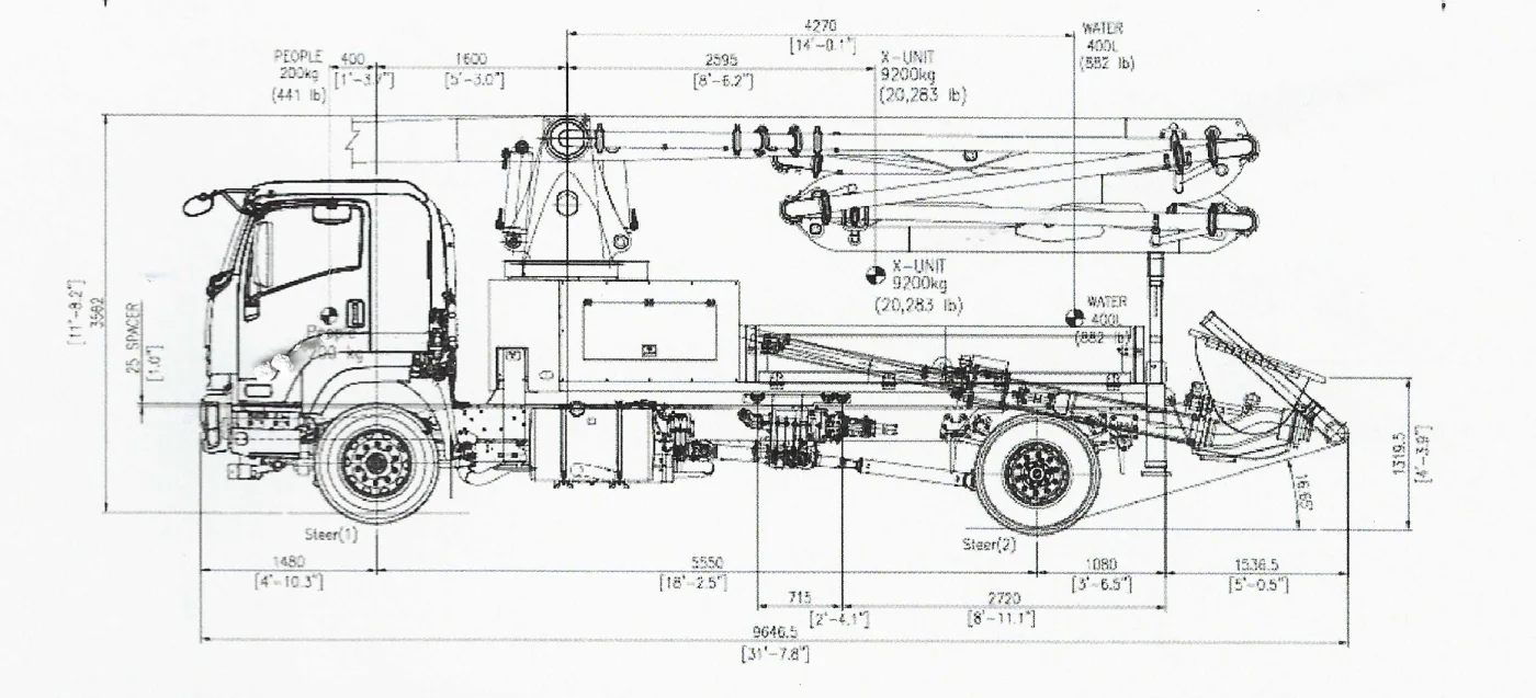
MACHINE ANATOMY
Select a numbered marker to highlight that system and see the published data for this model.
01 / MARKER
Sections, folding geometry, and the published operating reach.
02 / MARKER
The slewing structure and published rotation range.
03 / MARKER
Published output, pressure, cylinder, and stroke performance.
04 / MARKER
The footprint and stabilizer dimensions used to plan setup.
05 / MARKER
The published receiving-hopper capacity.
06 / MARKER
The hydraulic circuit and principal drive components.
07 / MARKER
On-machine water capacity and supporting cleanup pressure.
The water tank is not separately outlined in this side drawing.
08 / MARKER
Published pipe and end-hose dimensions for concrete delivery.
TECHNICAL DOCUMENTS
View, compare, and download the model drawings without leaving this page.